Free Electrode Placement
Free electrode placement
Not every montage comes from an EEG net. Free-hand placement lets you put electrodes wherever you want on a subject’s scalp by clicking them into place, and then run a simulation from that configuration like any other montage.
What’s new in v3. This was the Electrode Placement extension in 2.x — a separate window you opened from the Extensions menu. It is now part of the Simulator: the same 3-D pane the page already draws is the one you click on, and a saved placement is immediately a Source you can pick in a job row.
Full list: the v3.0.0 release notes.
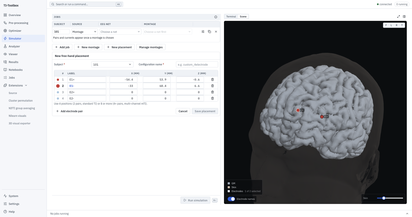 Two positions placed. The selected row (E1-) is labelled in the pane, and its dot carries a ring.
Placing electrodes
- On the Simulator, press New placement. The editor opens with four rows already named
E1+,E1-,E2+,E2-— the plan, before anything is clicked. - Choose the subject and give the configuration a name.
- Select a row, then click the head in the pane. That row takes the point you clicked, in that subject’s own millimetres. Clicking again moves it rather than adding another.
- Select the next row and click again. Each row has its own colour, and each dot is labelled.
Selection comes first, always: a click with no row selected places nothing. It is never ambiguous which electrode you are manipulating — the selected row’s swatch is the checked one, hovering a row lights its dot, and clicking a dot selects its row instead of dropping a second electrode on top of it.
Add electrode pair appends two more rows; the trash icon removes a row and its dot together — the table and the scalp are one state, never two that can disagree.
Coordinates are the subject’s
The Simulator’s pane is the only pane in the app that draws the selected subject. Every other 3-D pane (Optimizer, Analyzer) draws a fixed packaged guide head, and a click there names an electrode or an atlas region — never a coordinate. That is deliberate: the guide’s space is no research subject’s space, and a guide coordinate must never be written into a configuration that runs on a different head.
You can also type coordinates directly into the X/Y/Z fields, to 0.1 mm. That is the way to enter a position you already know — from a paper, from a previous study, or from a neuronavigation system.
How many positions
| Positions | Mode |
|---|---|
| 4 (2 pairs) | Standard TI |
| 8 or more, in steps of 2 | Multipolar TI (mTI) |
The mode is derived from the number of pairs — there is no separate switch to forget.
What is saved, and where
Save placement writes derivatives/SimNIBS/sub-<id>/m2m_<id>/stim_configs/<name>.json in your project. From then on it appears in a
Simulator job row when the Source column is set to Free-hand, alongside the montages that
came from EEG nets and the results that came from an optimizer.
Because it is a plain JSON file, it is also readable from a script or notebook, and it travels with the project.
Choosing positions well
- Use the pairs, not the electrodes, as the unit. TI is generated by the interaction of two carriers; the geometry that matters is where the two pairs cross.
- Watch the skin opacity slider. Turning the scalp translucent lets you see the cortex under the point you are about to click; the grey matter stays opaque so the anatomy under your cursor is never a blend of two surfaces.
- Anatomical plausibility is on you. Nothing checks that a position is reachable on a real head, that it clears an ear, or that two electrodes do not overlap. If you want positions the method chose rather than positions you chose, use flex-search.
Known limitation
A dot on the far side of the head is not hidden by the head, so a placement can look like it is on the near surface when it is not. Rotate before you trust an overlapping pair.